Table of Contents
Site and Service Conditions
The operating conditions are as follows:
a) Installation location: Outdoors, in direct sunlight.
b) Altitude: ≤ 2000 meters.
c) Maximum ambient temperature: 40°C
d) Average ambient temperature in any given year: 30°C
e) Average relative humidity in any given year: 79%.
f) Average maximum relative humidity in any given year: 94%. The switchgear should be suitable for use in tropical climates and should be capable of operating at full rated load under the above-mentioned environmental conditions.
Reference Standards
International Electrotechnical Commission (IEC)
IEC 62271-102 (2001) AC disconnectors and earthing switches. IEC 62271-103 (2011) Switchgear for rated voltages above 1 kV up to and including 52 kV.
Institute of Electrical and Electronics Engineers (IEEE)
IEEE C37.74-2003 IEEE Standard Requirements for Underground, Vault-Mounted, and Pad-Mounted Load-Break Switchgear and Fused Load-Break Switchgear for AC Systems Up to 38 kV
Technical parameters
Electrical Technical Parameters
a) Load-break switches conforming to IEC standards shall have the following characteristics
Rated voltage: 12 kV
Number of poles: 3
Rated frequency: 50 Hz
Rated lightning impulse withstand voltage: 75 kV
Rated power frequency withstand voltage: 28 kV
Rated normal current: 400 A
Rated breaking current: 400 A
Rated short-time withstand current (1 second): 20 kA
Rated peak withstand current: 50 kA
Rated short-circuit current (earthing switch): 50 kA
b) Load-break switches conforming to IEEE standards shall have the following minimum ratings. Rated voltage: 15.5kV
Number of poles: 3
Rated frequency: 50Hz
Rated lightning impulse withstand voltage: 95kV
Rated power frequency withstand voltage: 34kV
Rated continuous current: 400A
Rated switching current: 400A
Rated short-time withstand current (1s): 20kA
Rated peak withstand current: 32kA
Rated fault-making current (earthing switch): 32kA
Structural Features:
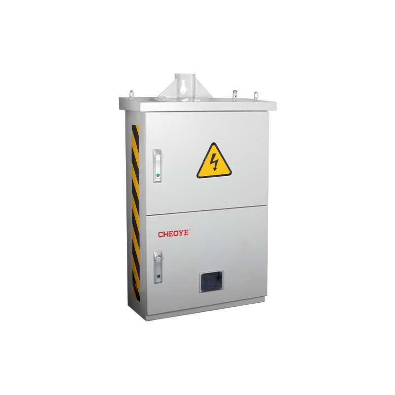
- The switchgear is an outdoor type, completely enclosed, and made of stainless steel, suitable for direct connection to the network transformer tank using bolts and nuts.
- SF6 pressure monitoring device.
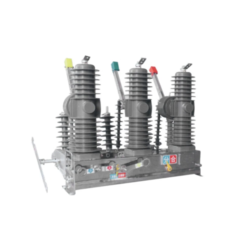
- The switchgear is either of the following types:
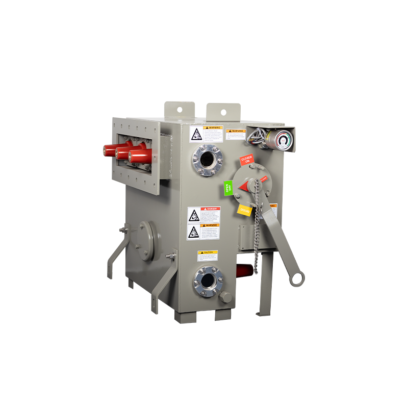
a) The switchgear includes a load-break switch and an earthing switch, as shown in Figure 1A. The load-break switch shall use SF6 as the arc extinguishing and insulating medium. The earthing switch shall use SF6 as the insulating medium. The load-break switch and earthing switch shall be equipped with a mechanical interlock to prevent the earthing switch from being connected when the load-break switch is in the “on” position.
b) The switchgear is a three-position load-break switch, including the on/off and earthing positions shown in Figure 1B. The switch shall use SF6 as the arc extinguishing and insulating medium.


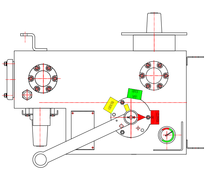
The switchgear operating handle is manually operated from a platform or the ground via a hook lever. The switch shall be equipped with the following two types of operating handles:
a) Load-break switch with earthing switch (Figure 1A). The switch includes two operating handles with interlocks: one for load-break operation and the other for earthing operation. The interlock prevents the earthing switch from opening when the load-break switch is in the “on” position.
(b) Three-position switch
The switch includes one operating handle for both load-break and earthing operation. The switch has a “safety” mechanism to prevent consecutive “earthing” operations during a single operation. For example, the handle can be moved to the earthing position by changing the handle position and removing the lock.
As shown in Figure 2, the handle switch should be operated from the street side and parallel to the platform. The handle can be permanently installed or removed for storage. The operating handle direction is clearly marked and the position is clearly visible from the side. Both handles lock in the open and closed positions. Label “open” and “close.”